Sunday, 22 April 2012

Diode Tutorial

Diodes are polarised, which means that they must be inserted into the PCB the correct way round. This is because an electric current will only flow through them in one direction (like air will only flow one way through a tyre valve).
Diodes have two connections, an anode and a cathode. The cathode is always identified by a dot, ring or some other mark.
Diodes anode cathode marking diagram
The pcb is often marked with a + sign for the cathode end.
Diodes come in all shapes and sizes.
They are often marked with a type number.
Detailed characteristics of a diode can be found by looking up the type number in a data book.
If you know how to measure resistance with a meter then test some diodes.
A good one has low resistance in one direction and high in the other.
Diode Symbols Diagram
There are specialised types of diode available such as the zener and light emitting diode (LED).

Cathode Ray Tube (CRT) Tutorial


Cathode Ray Tube (CRT) Diagram
The Cathode Ray Tube (CRT) is used in oscilloscopes, radar, monitors and television receivers. It consists of a glass envelope made from a neck and cone. All air has been extracted so that it contains a vacuum. At the narrow end are pins which make connection with an internal ELECTRON GUN. Voltages are applied to this gun to produce a beam of electrons. This electron beam is projected towards the inside face of the screen.
The face is coated with a PHOSPHOR which PHOSPHORESCES (glows) when hit by the beam. This produces a spot of light on the centre of the face of the CRT. By varying the beam current, spot BRIGHTNESS can be controlled. Controlling the diameter of the beam controls FOCUS. Phosphors come in a range of colours.
On its way from the gun to the screen the beam passes between  2 sets of plates. They are called the X and Y plates (as in graphs). By applying voltages to these plates the beam can be deflected. This causes the spot to move from the centre of the screen to another position on the screen. The X plates plates deflect the spot horizontally, the Y plates vertically. Thus the spot can be deflected to any position on the screen. External deflection coils are often used instead of the internal deflection plates.
Note that dropping a CRT causes it to IMPLODE which is as dangerous as an explosion.

Circuit Components Symbols Tutorial


The diagram below shows passive components, resistors, capacitors and inductors, and also electrical components such as switches, relays, motors and lamps. Also shown are the symbols for wires that are not joined (no physical electrical connection) and wires that are joined (a physical electrical connection).
Electronic Components Symbols Chart
This next diagram depicts active components, the difference between active and passive is that active components require a power source to work, whereas passive components do not. The top symbols represent vacuum tube or thermionic devices. Although at one time, these were being replaced by the smaller transistor and integrated circuits, they are finding their way back into electronics for use in professional audio equipment and some radio receivers
Transistors Components Symbols Chart

Saturday, 21 April 2012

Capacitors Tutorial

Capacitors are basically two parallel metal plates separated by an insulator.
Capacitor Internal Diagram
This insulator is called the dielectric. Capacitor types are named after the dielectric. Thus we have ceramic, mica, polyester, paper air capacitors etc.
Capacitors can be charged up and store electricity, similar to a car battery. This can be a hazard if they are charged up to high voltages. If it is necessary, capacitors with large charges should be discharged via a resistor to limit the discharge current. DC current cannot flow through a capacitor since the dielectric forms an open circuit.
Capacitors come in all shapes and sizes and are usually marked with their value. Values are measure in Farads. Values in Farads are unusual. Most capacitor values are measured in microfarads, nanofarads or picofarads. See the page on Value multipliers to find out more about this.
Capacitor Diagram
They are often marked with their maximum working voltage. The voltage across the terminals must not exceed this value. It is OK to use a voltage below the maximum value.Some capacitors such as electrolytic and tantalums are polarised. This means that they must be fitted the correct way round. They are marked to indicate polarity.
Some values are indicated with a colour code similar to resistors. There can be some confusion.
A 2200pf capacitor would have three red bands. These merge into one wide red band.
COLOR CODING OF CAPACITOR - Tolerance Diagram
Some values are marked in picofarads using three digit numbers. The first two digits are the base number and the third digit is a multiplier.For example, 102 is 1000 pF and 104 is 100,000 pF = 100 nF = 0.1 uF.
To find the total value of capacitors in parallel (that is connected across each other) their values are added. To find the total value if they are in series (that is in line with each other) then the following formula is used.
1/C total =1/C1 + 1/C2 + 1/C3 etc
Variable capacitors are available in which the value can be adjusted by controlling the amount of overlap of the plates or the distance between them.
Variable capacitors Diagram
There is a type of diode called the Varicap diode with similar characteristics.

Batteries Tutorial

Batteries are assembled from cells, connected in series, to increase the voltage available. In a cell chemical energy is converted into electrical energy.
Cells may be either PRIMARY or SECONDARY types. A primary cell is discarded when its chemical energy is exhausted. A secondary cell can be recharged. The most common primary cell is the zinc/carbon (Leclanche) as used in torches, portable radios etc.
Batteries - Dry Cell Diagram
The zinc and carbon react with the ammonium chloride ELECTROLYTE to produce electricity. The manganese dioxide absorbs hydrogen gas produced around the carbon rod which would insulate it from the electrolyte and stop the cell working.
The most common secondary cells are the lead/acid and nickel/cadmium (nicad). Lead acid batteries need a constant voltage charger. Nicads must be charged with a constant current charger.
All cells have INTERNAL RESISTANCE. This is not an actual resistor but a characteristic of the cell. Internal resistance increases as the cell ages.
INTERNAL RESISTANCE OF BATTERY Diagram
When current is taken from a battery, voltage is dropped across this internal resistance and the voltage at the battery terminals falls.
The diagram shows that as the current taken increases the terminal voltage decreases.
POOR REGULATION battery Diagram
This is called POOR REGULATION. It occurs in any type of power supply. Battery voltages must therefore always be measured ON LOAD, i.e. with the radio etc switched on and drawing current.

Active and Passive Tutorial

ACTIVE components increase the power of a signal and must be supplied with the signal and a source of power.
Examples are bipolar transistors, field effect transistors etc.
The signal is fed into one connection of the active device and the amplified version taken from another connection.
In a transistor, the signal can be applied to the base connection and the amplified version taken from the collector.
The source of power is usually a dc voltage from a battery or power supply.
PASSIVE components do not increase the power of a signal.
They often cause power to be lost.
Some can increase the voltage at the expense of current, so overall there is a loss of power.
Resistors, capacitors, inductors and diodes are examples of passive components.
Integrated circuits contain both active and passive components.
Since they usually increase the power of a signal and require a source of dc power they are treated as active devices.

7 Segment Display Tutorial

The 7 segment display is used as a numerical indicator on many types of test equipment.
7 Segment Display Diagram
It is an assembly of light emitting diodes which can be powered individually. They most commonly emit red light. They are arranged and labeled as shown in the diagram.
Powering all the segments will display the number 8.
Powering a,b,c d and g will display the number 3.
Numbers 0 to 9 can be displayed.
The d.p represents a decimal point.
The one shown is a common anode display since all anodes are joined together and go to the positive supply.
The cathodes are connected individually to zero volts.
Resistors must be placed in series with each diode to limit the current through each diode to a safe value.
Early wrist watches used this type of display but they used so much current that the display was normally switched off. To see the time you had to push a button.
Common cathode displays where all the cathodes are joined are also available.
Liquid crystal displays do a similar job and consume much less power.
Alphanumeric displays are available which can show letters as well as numbers.

Time Constants Tutorial

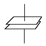
Like charges repel, unlike attract.  In the first diagram, when the switch is closed, the negative terminal of the battery repels the negative electrons and pushes them onto the upper plate of the capacitor C.
TIME CONSTANTS Diagram
Similarly, the positive terminal attracts the negative electrons away from the lower plate. If the battery is now removed, C remains charged up to the battery voltage. This can be dangerous, since capacitors can remain charged to high voltages for a long time. If a screwdriver is now placed across the capacitor terminals, the surplus electrons on the upper plate will now flow to the lower plate.
The C is now discharged.
Doing this can also be dangerous.
The screwdriver has a low resistance, and Mr Ohm says "low resistance means high current". One vapourised screwdriver !!
Therefore large, highly charged capacitors must be discharged via a resistor, to limit the amount of discharge current that can flow.
In the second diagram, a resistor R has been placed in series with C. When the switch is closed, C charges from the battery, as described previously. The charging current passes through R. Since R limits the amount of current that can flow (Ohms law), C takes time to charge up to the battery voltage.
The larger the values of C and R, the longer C takes to charge. Liken it to filling a bucket with a hosepipe. The larger the bucket (C), and the more you stand on the hosepipe (R), then the longer it takes to fill the bucket. The value of C in Farads, multiplied by the value of R in ohms, gives us the TIME CONSTANT (RC), measured in seconds.

If C = 2 Farads and R = 10 ohms then RC = 20 seconds. This means that C will take 20 seconds to charge up to 63 % of the battery voltage. If it is a 100 volt battery, then after 20 seconds, the capacitor voltage will be 63 volts.
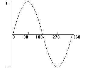
If we draw a graph of the increase of capacitor voltage against time, then we get a curve that is not linear ( not a straight line).
The curve is exponential. It increases rapidly at the start and then slows down. It gets slower and slower.
Time Constants Linear Exponential Diagram
If C is discharged, by connecting a resistor across it, then the capacitor voltage falls BY 63 % after RC seconds.
Time constants are often used where a time delay is required.
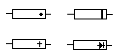
What is Phase Tutorial

The generator at the power station which produces our AC mains rotates through 360 degrees to produce one cycle of the sine wave form which makes up the supply.
WHAT IS PHASE diagram
In the next diagram there are two sine waves. They are out of phase because they do not start from zero at the same time. To be in phase they must start at the same time.
The waveform A starts before B and is LEADING by 90 degrees.
Waveform B is LAGGING A by 90 degrees.
PHASOR DIAGRAM
The last diagram, known as a PHASOR DIAGRAM, shows this in another way. The phasors are rotating anticlockwise as indicated by the arrowed circle.
A is leading B by 90 degrees.
The length of the phasors is determined by the amplitude of the voltages A and B. Since the voltages are of the same value then their phasors are of the same length. If voltage A was half the voltage of B then its phasor would be half the length of B.
All this has nothing to do with "set your phasors on stun".
PHASOR DIAGRAM

The RF Spectrum Tutorial

Frequency Range Classification
3 - 30 kilohertz30 - 300 kilohertz
300 - 3000 kilohertz (3 megahertz)
3  - 30 megahertz
30 - 300 megahertz
300 - 3000 (3 gigahertz)
3 gigahertz - 30 gigahertz
300 - 3000 gigahertz
Very low frequencies (VLF) The long wave band (LW)
The medium wave band (MW)
The short wave band (SW)
Very high frequency band (VHF)
Ultra high frequency band (UHF)
Super high frequency band (SHF)
Microwave frequencies
Higher in frequency than this are infra red, visible light, ultra violet, X rays etc. which are all forms of Electro Magnetic radiation.

The Integrator Tutorial

THE INTEGRATOR Diagram
We suggest you read the TIME CONSTANTS before tackling this one.
The integrator consists of a capacitor and resistor connected as shown.
A PULSE TRAIN is applied to the input.
When an input pulse rises rapidly to maximum the capacitor charges exponentially through the resistor as shown in the lower waveform.
When the input pulse falls suddenly to zero the capacitor discharges exponentially to zero. The process is repeated for each pulse giving the waveform shown.

The Differentiator Tutorial

Read the page on TIME CONSTANTS before trying this one.
DIFFERENTIATOR Diagram
The differentiator is made from a capacitor C, and resistor R, and assembled as shown. A PULSE TRAIN is applied to the input.
When a pulse of voltage rises suddenly from zero to maximum, the current which is charging C suddenly rises to a maximum value as well. As C charges, the charging current falls exponentially to zero.
Since this charging current is passing through R the voltage across R (which is the output voltage) does the same. Therefore we get the shape shown, with the voltage out rising suddenly to maximum and then falling exponentially to zero.
When the pulse falls to zero C discharges. The discharge current is high at the start and then falls exponentially to zero as C discharges.
However, since the discharge current is in the opposite direction to the charge current the voltage across across R will be reversed and so the waveform is now shown below the zero line. For each pulse the waveform out is repeated giving the display shown.
Ohms Law says that current is proportional to voltage. Conversely, voltage is proportional to current.

Source and Load Tutorial

The SOURCE is a source of power. The LOAD is powered by the source. Two terminals on the source are connected to two terminals on the load.
SOURCE  LOAD

battery

amplifier output

microphone

motor 

dynamo
 
amplifier

loudspeaker

amplifier

lathe

lamp
SOURCE AND LOAD
Current flows out of the source through one lead, through the load and then back to the battery via the other lead.
The value of the current flowing back to the battery is exactly the same as that leaving. Nothing is lost or gained.
To protect the load and source against excessive current flowing due to a fault, a fuse is inserted in one of the leads.

Sound Tutorial

  • Sound waves are caused by vibrations such as that from a tuning fork, a loudspeaker cone, or the human voice.
  • These vibrations need air to travel through. They cannot travel through a vacuum.
  • The air itself doesn't travel.
  • The sound causes compression and decompression of the air as it moves through it.
  • There is a regular spacing between one pressure peak and the next.
  • This distance is called the WAVELENGTH.
Sound Wave Length Diagram
  • Sound travels at about 330 metres a second.
  • A pure sound tone consists of a single frequency of vibration.
  • The range of human hearing is about 20 Hertz to 20 KiloHertz.
  • Most sounds are a mixture of frequencies. See the page on HARMONICS.
  • Microphones convert sound pressure waves into electrical signals.
  • Loudspeakers convert electrical signals into sound waves.
  • Loudspeakers and microphones are TRANSDUCERS.
  • Frequency, wavelength and the speed of sound are interrelated.
Wavelength x frequency = the speed of sound in metres per second.

Semiconductor Materials

The two most common materials used in the making of semiconductors are silicon and germanium. Sand on the beach is silicon and they say that germanium can be obtained from chimney soot.
So you can see that the raw materials are extremely common. However they do have to be purified to an extraordinary degree. When purified they have a crystalline construction like salt and sugar.
The atoms which make up the materials are rigidly locked together in a pattern (a LATTICE) in which the electrons, in the atoms, are unable to move. This means that pure silicon and germanium are good insulators.
After purification, precise amounts of impurities are added (the materials are DOPED).
These impurities fit into the lattice but have associated electrons which are free to move about and produce a flow of electric current.
There is therefore a surplus of negative electrons and the material is called N-type semiconductor.
Other types of impurities can be added to pure silicon and germanium. These produce a shortage of electrons in the lattice. Therefore there are HOLES in the lattice. Electrons can jump into these holes, producing a flow of holes. It's like sitting in a row of chairs in the doctor's waiting room.
When someone gets up and goes into the surgery there is an empty chair (a hole). People (electrons) move along nearer to the surgery and a hole travels in the opposite direction.
Since there is a shortage of negative electrons there is an overall positive charge and the material is called  P-type semiconductor.
The resistance of semiconductors is about half way between conductors and insulators. Hence the name, semiconductors.
Semiconductors are used in semiconductor devices such as diodes, transistors, integrated circuits etc.

RMS and Peak to Peak Tutorial

If someone measures the value of the AC voltage coming out of a transformer using an oscilloscope and says it is 20 volts peak to peak and we use a voltmeter to confirm this we will find that the meter reads only 7.07 volts.
This is because the scope measures peak to peak values and the meter measures RMS values.
In figure 1 the 'scope displays the peak value. The peak to peak voltage is twice this. For example if the peak is 10 volts then the peak to peak is 20 volts.
When using a meter to measure the same AC voltage a different value is obtained. This is because, as we said, meters measure RMS values.
A Root Mean Square (RMS) voltage gives the same heating effect as a DC voltage of the same value.  See figures 2 and 3. Both thermometers show the same temperature when the resistors are heated by the current passing through them.
RMS values can be converted to peak to peak values and vice-versa.
RMS values times 1.414 equals the Peak value. Peak to Peak is twice this. 7.07 volts RMS times 1.414 and then doubled is 20 volts, the Peak to Peak value.
RMS AND PEAK TO PEAK Diagram
Peak values times 0.707 gives the RMS value. Don't forget that Peak is half the Peak to Peak.
20 volts Peak to Peak is 10 volts Peak.
10 volts Peak times 0.707 equals 7.07 volts RMS.

Pulses Tutorial

Here is the characteristics of a single pulse.
Single Pulse Diagram
  • The voltage rises very rapidly from zero to its maximum value.
  • It stays steady at the maximum value for a time.
  • It then falls very rapidly back to zero.
  • The duration of a pulse can be anywhere from a very long time (days) to a very short time (picoseconds or less).
  • Pulses do not rise and fall instantaneously but take time (which may be very short).
  • They are called the RISE and FALL times.
Pulse Train Diagram
If pulses occur one after another they are called a PULSE TRAIN.
The duration time of a pulse is called the MARK.
The time between pulses is called the SPACE.
The relative times are expressed as the MARK/SPACE RATIO.
Mark/space ratios can vary.
PULSES Square Wave Diagram
Fig. 3 has a 50:50 mark/space ratio.
This is a special case called a SQUARE WAVE.
Fig. 4 is about 1:10
Fig. 5 is about 10:1
Note that the last three waveforms are of the same frequency. All the pulses start at the same instant.

Pulse Modulation Tutorial

Pulse modulation consists of switching the carrier on and off as required.
Fig.1 shows a continuous wave carrier (CW).
PULSE MODULATION - Continous Wave Carrier - CW Diagram
Fig.2 shows the carrier being switched on for a short time to produce a pulse of R.F.
PULSE MODULATION Diagram
This is the principle of Radar; a short pulse is transmitted and then an echo listened for.
Fig.3 shows a long pulse and three short ones.
principle of Radar Diagram
This generates the letter B in Morse Code.
Fig.4 shows Pulse Width Modulation (PWM).
Pulse Width Modulation PWM Diagram
The width of the pulse is determined by the amplitude of the modulating signal at that instant.
Fig. 5 shows Pulse Position Modulation (PPM).
Pulse Position Modulation (PPM) Diagram
Here the width and amplitude of the pulse are constant but its position is determined by the amplitude of the modulating signal.
PULSE CODE MODULATION is where the amplitude of the modulation is measured at regular intervals and a binary number generated to represent that amplitude.

Percent and Tolerance Tutorial

1% of anything is one hundredth part of it.
1% of 100 balls is 1 ball.
1% of 500 is 500/100 = 5.
10% of anything is 10 x 1%.
1% of 1000 tons is 10 tons.
10% is 100 tons.
5% is 50 tons.
1% of 100 ohms is 1 ohm.
5% of 100 ohms is 5 ohms.
A 100 ohm resistor with a tolerance of 5% can have a value between 95 and 105 ohms and be within tolerance.

Oscillators Tutorial

Oscillators are amplifiers with such a large amount of positive feedback that they produces an output signal with no signal applied to the input.
Oscillator Feedback Amplifier Diagram
The output amplitude is determined by the gain of the amplifier and the feedback circuit.
Oscillators can produce sine waves, the frequency of which is determined by TUNED CIRCUITS.
Tuned circuits consist of a capacitor and inductance. Square wave oscillators use resistors and capacitors to determine the frequency of oscillation.
Ideally the frequency of an oscillator should be stable, but due to temperature variations and mechanical vibration this may not be so. Precautions are taken against frequency DRIFT.
"Howl round", caused by placing a microphone too close to a loudspeaker, is an audio oscillation caused by positive feedback.

Ohms & Kirchhoff's Law Tutorial

 Ohms & Kirchhoff's Law

Kirchhoff's Current Law

The algebraic sum of currents entering and leaving any point in a circuit must equal zero.
Stated another way
No matter how many paths into and out of a single point all the current leaving that point must equal the current arriving at that point.
Ohms & Kirchhoff's Law

Kirchhoff's Voltage Law

The algebraic sum of the voltages around any closed path is zero.
 
Stated another way
The voltage drops around any closed loop must equal the applied voltages.
When voltages are opposing as seen at the right, the difference is the voltage applied to the circuit. In this case 4 volts must be dropped by the resistors to equal the applied voltage

Motor Principle

It is best if you read the page on the Magnetism first.
When a current is passed through a wire which is suspended in a magnetic field, the wire will move. The direction of movement is determined by the direction of the field and the direction of the current. The speed of movement is determined by the strength of the field and the amplitude of the current.
Motor Principle Diagram
This principle is used in the electric motor to produce rotation. It is also used in the loudspeaker where varying speech currents through a coil, suspended in a magnetic field, causes movement of a cone, resulting in sound pressure waves.
The moving coil meter uses the same idea. When the meter is connected to a circuit, current passes through a coil. The coil is suspended in a magnetic field, and rotates when current passes through it. A pointer fixed to the coil indicates a value on a scale.
The Electric Generator Principle is related. Here a coil is moved in a magnetic field. This induces voltages and current in the coil.

Mixer Tutorial

The mixer has two input signals of different frequencies, f1 and f2.
MIXER
These inputs are mixed together in the mixer. (some books say "beaten" together, others say "heterodyned").
f1 and f2 then come out of the mixer, together with two new frequencies.
One of the new frequencies is the sum of the two inputs, f1 + f2.
The other is the difference between the two inputs, f1 - f2.
For example, if the inputs are 1 Mhz and 1.47 MHz then the sum frequency is 2.47 MHz. The difference frequency is 0.47 MHz (470 kHz).
Sometimes, on the radio, two adjacent stations will produce an interfering whistle. This is because their frequencies are close enough to beat together. The difference between their frequencies is in the audio range.
If you have two racks of equipment, cooled by fans, the noise produced by each fan rotating often beats together to give a low frequency beat noise.
Mixers are used as part of the FREQUENCY CHANGER in radios. Understanding mixers will help you to understand the MODULATION process in A.M. transmitters.

Magnetism Tutorial

Some irons, when dug up, attract other metals. They are called MAGNETS. The reason that they are magnetic is that their DOMAINS are aligned.
MAGNETISM Diagram
One end of a bar magnet is the NORTH POLE, the other end the SOUTH POLE.
A rule of magnetism is that LIKE POLES REPEL, UNLIKE POLES ATTRACT. North attracts South and repels North etc. The North pointer on a compass is actually a South pole since it is attracted by the North pole of the earth.
A magnet is surrounded by an invisible MAGNETIC FIELD made of magnetic LINES OF FORCE
These lines of force can be made visible by covering a magnet with a sheet of paper and sprinkling iron filings on the paper.
MAGNETISM Force North to South Diagram
The lines of force run from north to south.
Lines of force pass through all materials including insulators.  They pass through some more easily than others. These are said to have a lower RELUCTANCE.  Iron has a lower reluctance than air.
The lines of force prefer to pass through lower reluctance materials.
Magnetism Air Soft Iron North South Diagram
PERMANENT magnets are made of steel or steel alloys. Brass, copper and aluminum do not magnetize.

Light Tutorial

Light is an electromagnetic wave similar to radio waves. It has wavelength and frequency. It travels at 300,000,000 metres per second.
Light Mirror Diagram
Wavelength, frequency and the speed of light are related. Wavelength x frequency = the speed of light. Different colours of light have different frequencies.
When a ray of light hits a shiny surface it is REFLECTED. The angle of reflection equals the angle of incidence.
Light Air Glass Diagram
When light passes from one transparent material to another it is REFRACTED (bent).
LENSES use refraction. CONVEX lenses FOCUS a beam of light to a point.
Focal Point Convex Lens Diagram
CONCAVE lenses cause the beam to DIVERGE.
Concave Lens Diagram
The PRIMARY colours which make up white light can be separated out by a glass PRISM.
Light Prism Diagram
Three of the primary colours, RED, GREEN and BLUE are used in the colour television system.
By mixing them most other colours can be made.
In the next diagram, red and green make yellow, green and blue make cyan and red and blue make magenta.
Light Three Colours Mixing Diagram
White is made by using all three colours.

Heat Tutorial

When an object is heated above the temperature of its surroundings it will lose heat to the surroundings.
Heat is transferred in three ways.
1.   CONDUCTION
  • If one end of a metal bar is heated then heat is transferred by conduction to the cold end.
  • Good electrical conductors such as copper and gold are  good conductors of heat.
  • Poor electrical conductors, such as wood and paper, are poor heat conductors.
  • Heat can be conducted between two objects if they are in close contact.
  • For example between a soldering iron and a soldering terminal; or between a power transistor and its heat sink.
2.   CONVECTION
  • Here, heat is transferred by the movement of a gas or a liquid.
  • Hot air rises and cold air falls. Liquids behave in a similar manner.
  • A hot resistor causes convection, transferring heat from the resistor to the surrounding air.
  • Hot water in a pan rises to the top while the cold water  falls to the bottom.
  • These movements are called convection currents (nothing to do with electric currents).
  • The above process is called NATURAL CONVECTION.
  • If a fan is used to aid convection it is called FORCED CONVECTION.
3.   RADIATION
  • This does not need a gas or liquid to transfer the heat.
  • Heat is expelled  mostly in the form of infrared radiation.
  • This is a form of light and travels at the speed of light.
  • It can travel through a vacuum.
  • This is why we can feel the heat of the sun even though it has to travel through the vacuum of space to reach earth.
  • Polished surfaces are poor radiators but good reflectors of heat. That is why electric fires have shiny reflectors.
  • Black objects are good radiators.
4.  THE EFFECTS OF HEAT
  • Heat causes solid objects to expand.
  • That is why they have gaps in railway lines and bridges to allow for summertime temperatures.
  • Different metals expand at different rates.
  • A temperature switch can be made from two strips of dissimilar metals fixed together.
  • As the temperature increases, one strip grows longer than the other, causing the strips to curve. This in turn breaks (or makes) a circuit.
Heat Cold Hot Diagram
  • Increasing temperatures also cause liquids to expand. This behaviour  is used in the thermometer.
  • Gases also expand with temperature increases.
5.   HEAT AND ELECTRONICS
  • Heat is one of the biggest enemies of electronics, causing components to fail.
  • To minimize the effects some action can be taken.
  • Increasing the surface area increase convection and radiation. High wattages resistors are larger than low wattage ones.
  • Using holes and louvers in the casing increases natural convection.
  • Using fans provides forced convection.
  • Using heat sinks with fins increases surface area thus providing increased convection and radiation.
  • Painting heat sinks blacks increases radiation.
  • Using "heat sink compound", which is a good conductor, between transistors and their heatsinks, improves heat conduction.
  • Fitting components onto the metal chassis aids the dissipation of heat.

Harmonics Tutorial

When the same note, say middle C, is played on different instruments, the musical notes produced sound different. This is because that as well as producing the FUNDAMENTAL FREQUENCY of middle C they also produce multiples of this frequency called HARMONICS.
The fundamental is a pure sine wave.
HARMONICS - Pure Sine Wave Diagram
The number and amplitude of the harmonics determines the characteristic sound of the instrument.
The harmonic which is twice the fundamental frequency, as in the diagram, is called the 2nd harmonic.
The frequency which is three times the fundamental is the 3rd harmonic.
The 3rd, 5th, 7th etc are called ODD harmonics.
The 2nd, 4th, 6th, 8th etc are called EVEN harmonics.
A square wave is made up from a fundamental frequency sine wave and an infinite number of odd harmonics.
A sawtooth wave form consists of a fundamental plus an infinite number of even harmonics.
If a sine wave is injected into an amplifier the output wave form may be distorted. This may be due to harmonics being generated by the amplifier.

Graphs and Waveforms Tutorial

Graphs are one way of showing the relationship between two variables (things that can change in value).
GRAPHS AND WAVE FORMS Diagram
The graph above shows how the brightness of the sun is related to the time of day.
From the start at the bottom left hand corner until just before 6 am brightness is zero. (It is dark). Brightness increases as time passes being at maximum about 1 pm when the sun is highest in the sky. Brightness then falls becoming dark at about 9 pm when the sun sets. Now look at the following graph.
GRAPHS AND WAVE FORMS
This relates a dry battery voltage to time. It falls slowly over the weeks.
This next graph shows a voltage which slowly rises from zero to a maximum value and then falls suddenly to zero again.
GRAPHS AND WAVE FORMS
This next graph shows the same thing happening but continues repeating. This is called a WAVEFORM.
GRAPHS AND WAVE FORMS
The next waveform is called a square waveform because of its shape. It is at zero for a time and then shoots rapidly to a maximum value and stays there for a time before falling to zero again.  It then repeats itself continuously.
GRAPHS AND WAVE FORMS
An OSCILLOSCOPE is used to display and measure waveforms.
A common waveform is the SINEWAVE which can alternate between positive and negative voltages.
SINEWAVE GRAPHS AND WAVE FORMS
Note that the horizontal line in all these graphs is called the X axis and the vertical line is the Y axis.

Sample Text

Sample text

Social Icons

Featured Posts