Slide Title 1

Aenean quis facilisis massa. Cras justo odio, scelerisque nec dignissim quis, cursus a odio. Duis ut dui vel purus aliquet tristique.

Slide Title 2

Morbi quis tellus eu turpis lacinia pharetra non eget lectus. Vestibulum ante ipsum primis in faucibus orci luctus et ultrices posuere cubilia Curae; Donec.

Slide Title 3

In ornare lacus sit amet est aliquet ac tincidunt tellus semper. Pellentesque habitant morbi tristique senectus et netus et malesuada fames ac turpis egestas.

Sunday, 22 April 2012

Diode Tutorial

Diodes are polarised, which means that they must be inserted into the PCB the correct way round. This is because an electric current will only flow through them in one direction (like air will only flow one way through a tyre valve).
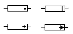
Diodes have two connections, an anode and a cathode. The cathode is always identified by a dot, ring or some other mark.
Diodes anode cathode marking diagram
The pcb is often marked with a + sign for the cathode end.
Diodes come in all shapes and sizes.
They are often marked with a type number.
Detailed characteristics of a diode can be found by looking up the type number in a data book.
If you know how to measure resistance with a meter then test some diodes.
A good one has low resistance in one direction and high in the other.
Diode Symbols Diagram
There are specialised types of diode available such as the zener and light emitting diode (LED).

Cathode Ray Tube (CRT) Tutorial


Cathode Ray Tube (CRT) Diagram
The Cathode Ray Tube (CRT) is used in oscilloscopes, radar, monitors and television receivers. It consists of a glass envelope made from a neck and cone. All air has been extracted so that it contains a vacuum. At the narrow end are pins which make connection with an internal ELECTRON GUN. Voltages are applied to this gun to produce a beam of electrons. This electron beam is projected towards the inside face of the screen.
The face is coated with a PHOSPHOR which PHOSPHORESCES (glows) when hit by the beam. This produces a spot of light on the centre of the face of the CRT. By varying the beam current, spot BRIGHTNESS can be controlled. Controlling the diameter of the beam controls FOCUS. Phosphors come in a range of colours.
On its way from the gun to the screen the beam passes between  2 sets of plates. They are called the X and Y plates (as in graphs). By applying voltages to these plates the beam can be deflected. This causes the spot to move from the centre of the screen to another position on the screen. The X plates plates deflect the spot horizontally, the Y plates vertically. Thus the spot can be deflected to any position on the screen. External deflection coils are often used instead of the internal deflection plates.
Note that dropping a CRT causes it to IMPLODE which is as dangerous as an explosion.

Circuit Components Symbols Tutorial


The diagram below shows passive components, resistors, capacitors and inductors, and also electrical components such as switches, relays, motors and lamps. Also shown are the symbols for wires that are not joined (no physical electrical connection) and wires that are joined (a physical electrical connection).
Electronic Components Symbols Chart
This next diagram depicts active components, the difference between active and passive is that active components require a power source to work, whereas passive components do not. The top symbols represent vacuum tube or thermionic devices. Although at one time, these were being replaced by the smaller transistor and integrated circuits, they are finding their way back into electronics for use in professional audio equipment and some radio receivers
Transistors Components Symbols Chart

Saturday, 21 April 2012

Capacitors Tutorial

Capacitors are basically two parallel metal plates separated by an insulator.
Capacitor Internal Diagram
This insulator is called the dielectric. Capacitor types are named after the dielectric. Thus we have ceramic, mica, polyester, paper air capacitors etc.
Capacitors can be charged up and store electricity, similar to a car battery. This can be a hazard if they are charged up to high voltages. If it is necessary, capacitors with large charges should be discharged via a resistor to limit the discharge current. DC current cannot flow through a capacitor since the dielectric forms an open circuit.
Capacitors come in all shapes and sizes and are usually marked with their value. Values are measure in Farads. Values in Farads are unusual. Most capacitor values are measured in microfarads, nanofarads or picofarads. See the page on Value multipliers to find out more about this.
Capacitor Diagram
They are often marked with their maximum working voltage. The voltage across the terminals must not exceed this value. It is OK to use a voltage below the maximum value.Some capacitors such as electrolytic and tantalums are polarised. This means that they must be fitted the correct way round. They are marked to indicate polarity.
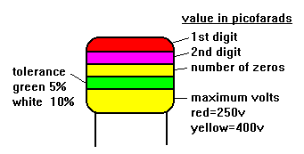
Some values are indicated with a colour code similar to resistors. There can be some confusion.
A 2200pf capacitor would have three red bands. These merge into one wide red band.
COLOR CODING OF CAPACITOR - Tolerance Diagram
Some values are marked in picofarads using three digit numbers. The first two digits are the base number and the third digit is a multiplier.For example, 102 is 1000 pF and 104 is 100,000 pF = 100 nF = 0.1 uF.
To find the total value of capacitors in parallel (that is connected across each other) their values are added. To find the total value if they are in series (that is in line with each other) then the following formula is used.
1/C total =1/C1 + 1/C2 + 1/C3 etc
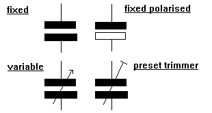
Variable capacitors are available in which the value can be adjusted by controlling the amount of overlap of the plates or the distance between them.
Variable capacitors Diagram
There is a type of diode called the Varicap diode with similar characteristics.
Batteries Tutorial

Batteries are assembled from cells, connected in series, to increase the voltage available. In a cell chemical energy is converted into electrical energy.
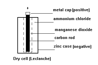
Cells may be either PRIMARY or SECONDARY types. A primary cell is discarded when its chemical energy is exhausted. A secondary cell can be recharged. The most common primary cell is the zinc/carbon (Leclanche) as used in torches, portable radios etc.
Batteries - Dry Cell Diagram
The zinc and carbon react with the ammonium chloride ELECTROLYTE to produce electricity. The manganese dioxide absorbs hydrogen gas produced around the carbon rod which would insulate it from the electrolyte and stop the cell working.
The most common secondary cells are the lead/acid and nickel/cadmium (nicad). Lead acid batteries need a constant voltage charger. Nicads must be charged with a constant current charger.
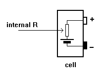
All cells have INTERNAL RESISTANCE. This is not an actual resistor but a characteristic of the cell. Internal resistance increases as the cell ages.
INTERNAL RESISTANCE OF BATTERY Diagram
When current is taken from a battery, voltage is dropped across this internal resistance and the voltage at the battery terminals falls.
The diagram shows that as the current taken increases the terminal voltage decreases.
POOR REGULATION battery Diagram
This is called POOR REGULATION. It occurs in any type of power supply. Battery voltages must therefore always be measured ON LOAD, i.e. with the radio etc switched on and drawing current.

Active and Passive Tutorial

ACTIVE components increase the power of a signal and must be supplied with the signal and a source of power.
Examples are bipolar transistors, field effect transistors etc.
The signal is fed into one connection of the active device and the amplified version taken from another connection.
In a transistor, the signal can be applied to the base connection and the amplified version taken from the collector.
The source of power is usually a dc voltage from a battery or power supply.
PASSIVE components do not increase the power of a signal.
They often cause power to be lost.
Some can increase the voltage at the expense of current, so overall there is a loss of power.
Resistors, capacitors, inductors and diodes are examples of passive components.
Integrated circuits contain both active and passive components.
Since they usually increase the power of a signal and require a source of dc power they are treated as active devices.

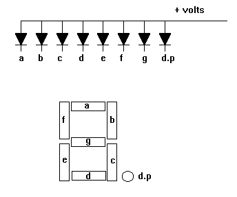
7 Segment Display Tutorial

The 7 segment display is used as a numerical indicator on many types of test equipment.
7 Segment Display Diagram
It is an assembly of light emitting diodes which can be powered individually. They most commonly emit red light. They are arranged and labeled as shown in the diagram.
Powering all the segments will display the number 8.
Powering a,b,c d and g will display the number 3.
Numbers 0 to 9 can be displayed.
The d.p represents a decimal point.
The one shown is a common anode display since all anodes are joined together and go to the positive supply.
The cathodes are connected individually to zero volts.
Resistors must be placed in series with each diode to limit the current through each diode to a safe value.
Early wrist watches used this type of display but they used so much current that the display was normally switched off. To see the time you had to push a button.
Common cathode displays where all the cathodes are joined are also available.
Liquid crystal displays do a similar job and consume much less power.
Alphanumeric displays are available which can show letters as well as numbers.

Sample Text

Sample text

Social Icons

Featured Posts